


Robots dominate modern game design and VFX pipelines. Studios need mechanical characters that move convincingly, hold up under close camera angles, and still run smoothly on target hardware. Building a great 3D robot model takes more than sculpting metal plates. You need clean topology, believable joints, and an export pipeline that survives contact with a real game engine.
This guide walks through the full production path for 3D robot models from early blockout to final engine import. Whether you’re grabbing free 3D robot models for a prototype or building a rigged 3D robot model from scratch for a shipping title, you’ll find the technical checkpoints that separate amateur work from production-ready assets.
Categories and Use Cases
Not every robot asset serves the same purpose. Before you open Blender or Maya, decide which category your project actually needs. The wrong choice wastes weeks of modeling time.
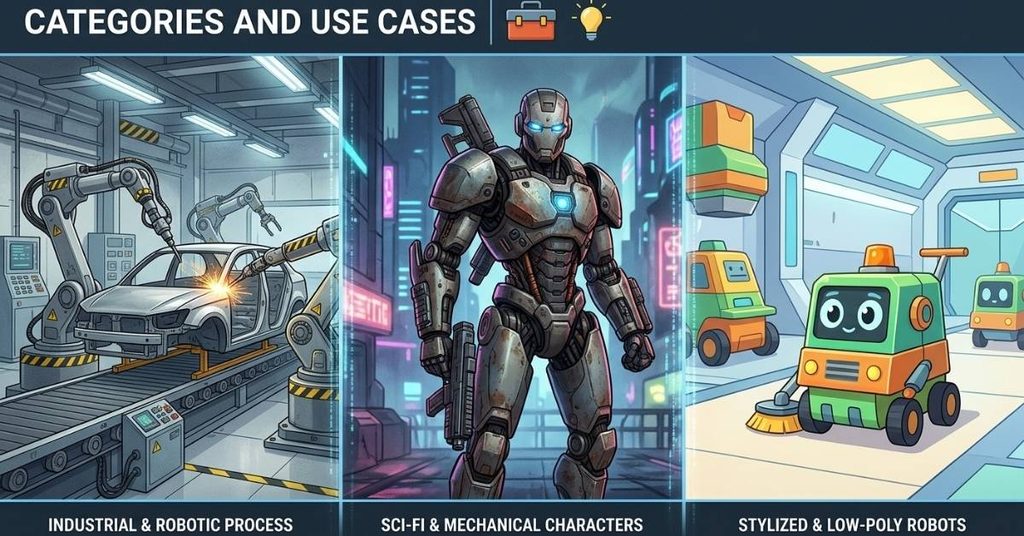
Industrial & Robotic Process Models
These models exist for accuracy, not drama. Manufacturing visualizations, robotic arm simulations, and training software all rely on precise scale and correct mechanical proportions. Polycount matters less here than dimensional accuracy. A misaligned pivot point can throw off an entire simulation.
Engineers often import CAD data directly, then retopologize it for real-time viewers. The goal stays functional: show how the machine moves, not how it looks under dramatic lighting.
Sci-Fi & Mechanical Character Models
This category gets the most attention online. Sci-fi robot 3D models built for games and film prioritize silhouette, personality, and screen presence. Artists push panel lines, exposed hydraulics, and battle damage to sell a sense of history and function.
A cinematic robot can carry a much higher polygon budget than a game asset. VFX renders don’t care about frame rate. Game engines do.
Stylized & Low-Poly Robots
Low-poly robot 3D models trade detail for performance. Mobile games and VR experiences demand tight polycounts and small texture sets. Artists lean on strong shape language and flat-shaded or simplified PBR materials to keep the silhouette readable without expensive geometry.
Good stylization isn’t a shortcut. It actually requires more design discipline, since every polygon has to earn its place.
Hard-Surface Modeling Workflows for Robot Assets
Hard-surface modeling for robotics differs from organic character work in almost every way. Surfaces stay rigid. Edges stay sharp. Symmetry rules the process.

Sub-D vs. Boolean-Centric Workflows
Two schools dominate hard-surface work. Sub-D (subdivision surface) modeling relies on clean quad topology and support loops to hold sharp edges under a subdivision modifier. It gives you smooth, production-clean results but takes longer to plan.
Boolean-centric workflows cut and combine shapes first, then clean up the resulting mesh afterward. This method moves faster during blockout and concept iteration, but it leaves messy topology that needs manual retopology before rigging or baking.
Most professional pipelines blend both. Artists block out major forms with booleans, then convert final hero pieces to Sub-D for the shots or angles that need it.
Maintaining Mechanical Functionality: Joints, Hydraulics, and Cabling
A robot only looks real if its mechanical logic makes sense. Every piston should look like it can actually extend. Every cable should have somewhere to route without clipping through armor plates.
Study real machinery before designing joints. Excavator arms, industrial robotic arms, and even bicycle suspension systems all show how engineers solve rotation and load-bearing problems. Borrow that logic and your robot reads as functional, not just decorative.
Topology Guidelines: Edge Loops for Hard Metal Surfaces
Edge flow on hard-surface models exists to control shading, not to support deformation, except at joints. Add support loops close to hard edges to prevent pinching under subdivision. Keep panel lines separated by actual geometry rather than just normal map details when the camera will get close.
At mechanical joints elbows, knees, shoulder pistons increase edge density. These areas deform during animation, and thin topology here causes visible stretching and mesh collapse.
Topology & Edge-Flow Benchmarks: A Real-World Case Study
Polygon budgets vary wildly depending on platform and use case. Here’s a side-by-side teardown comparing a mobile game robot asset against a cinematic VFX robot, based on typical production benchmarks.
| Metric | Mobile Game Robot (~15,000 tris) | Cinematic VFX Robot (~150,000 tris) |
| Vertex Count | ~7,500 | ~75,000 |
| Draw Calls (avg.) | 2–3 | 8–12 |
| Texture Set Size | 1x 2K PBR set | 4x 4K PBR sets |
| Normal Map Detail | Baked from mid-poly | Baked from ultra-high sculpt |
| Frame-Rate Impact (UE5, mobile target) | Negligible | N/A (offline render) |
| Frame-Rate Impact (Unity, mid-tier PC) | <0< 0.1 ms per instance | N/A (offline render) |
| Joint Edge-Loop Density | Low, simplified | High, deformation-safe |
| LOD Levels Required | 2–3 | 0 (single render pass) |
The gap between these two assets isn’t about skill. It’s about intent. A mobile robot needs to survive dozens of on-screen instances at once. A cinematic robot needs to survive a hero close-up. Matching your topology decisions to the actual use case saves enormous rework later.
Deformation and Joint Density
Mechanical joints need extra edge loops specifically at the elbow, piston, and ball-joint areas. Without them, the mesh pinches or stretches when the rig rotates past 45 degrees. A quick heatmap test, rotating each joint to its animation extremes and checking for shading artifacts, catches this problem before it reaches the rigging stage.
Texturing and PBR Material Setup
Texturing sells the illusion of weight and material. A robot with perfect topology still looks fake with flat, untextured metal.

Creating Realistic Wear, Scratches, and Edge Wear
Real metal never stays pristine. Edge wear, grime buildup in recessed panel lines, and scratches along high-contact surfaces all add believability. Substance 3D Painter’s generators handle most of this automatically, using curvature and ambient occlusion masks to place wear exactly where physics would put it.
Avoid overdoing it. Uniform, heavy wear across the entire surface reads as a texture filter, not a lived-in machine. Concentrate damage on edges, seams, and areas near moving parts.
Setting Up PBR Map Channels: Metallic, Roughness, and Normal
A standard PBR texturing workflow for metallic surfaces needs these core maps:
- Base Color (Albedo): Raw color information, free of baked lighting or shadows.
- Metallic: Defines which areas behave as metal versus non-metal (rubber gaskets, plastic housings).
- Roughness: Controls how sharp or diffuse reflections appear across the surface.
- Normal: Adds simulated surface detail from the high-poly bake.
- Ambient Occlusion: Reinforces contact shadows in crevices and panel gaps.
- Emissive: Powers glowing elements like status lights or power cores.
Each channel needs to work together. A high roughness value on a supposedly polished chrome panel will kill the metallic look no matter how correct the other maps are.
UV Unwrapping Strategies for Complex Mechanical Parts
Mechanical models often have dozens of small, separate parts. Group similar-scale pieces into shared UV tiles to keep texel density consistent. Straight, hard-surface edges usually unwrap cleanly along seams that already exist as panel lines, which also hides seam artifacts.
Keep texel density uniform across the whole model. Inconsistent density becomes obvious the moment you apply a tiling scratch or grime texture, since some parts will look blurrier than others.
The 5-Phase Hard-Surface Protocol
Here’s a proprietary-style production workflow that keeps hard-surface robot projects organized from concept to final asset.

Phase 1: Silhouette & Blockout
Nail the proportions before adding a single bolt or panel line. A strong silhouette should read the character’s role heavy tank-bot, agile scout-bot, humanoid assistant from a plain gray blockout alone.
Phase 2: Panel Cutting & Beveling
Use non-destructive modifier stacks (Bevel and Boolean modifiers in Blender, or similar live operations in Maya) to cut panel lines and add surface breakup. Keeping this stage non-destructive means you can adjust proportions later without starting over.
Phase 3: Mechanical Joint Articulation
Design joints so they physically make sense in motion. Test rotation ranges early. Pistons, wires, and plates should never clip into each other at full extension or full compression.
Phase 4: High-to-Low Bake Pipeline
Bake your high-poly detail down onto the optimized low-poly mesh using Substance 3D Painter. This stage generates Normal, Ambient Occlusion, and Curvature maps that carry all the fine detail without the geometry cost.
Phase 5: Engine Import & Shader Setup
Assign your PBR maps correctly inside the target engine. Roughness, Metallic, Base Color, and Emissive channels each need to map to the right shader input. A mismatched channel here undoes all the careful texturing work from Phase 4.
Rigging and Animating Mechanical Structures
A perfectly modeled robot still needs a rig that respects its mechanical nature. Robots don’t bend like organic characters, and treating them the same way during rigging leads to broken, unnatural motion.
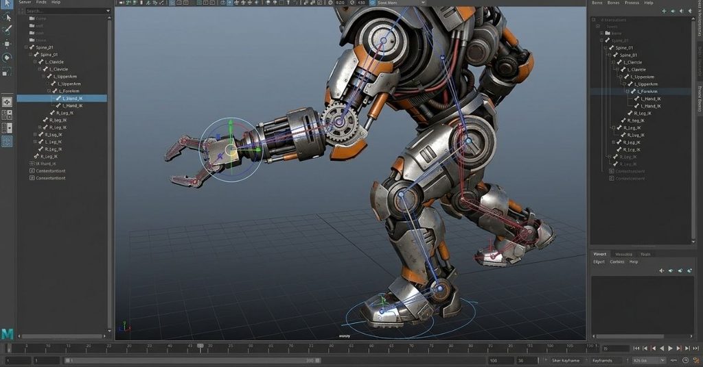
Setting Up Inverse Kinematics (IK) for Robotic Limbs
Inverse Kinematics (IK) rigging for mechanical joints lets animators pose an entire limb by moving just the end effector foot or hand while the rest of the chain solves automatically. This suits robot legs and arms well, since mechanical limbs usually move with clear, purposeful end goals (plant the foot, grab the object).
Avoiding Mesh Clipping in Joint Articulation
Clipping happens when armor plates or cables don’t account for the full rotation range of a joint. Test every joint at its animation extremes, not just a relaxed pose. Add corrective shapes or hide overlapping geometry inside a joint housing to mask any remaining clipping.
Hierarchy and Bone Naming Conventions for Game Engines
Consistent bone naming saves enormous time during animation retargeting. Stick to a clear left/right prefix system and a logical parent-child hierarchy that mirrors the robot’s actual mechanical structure. Game engines like Unity and Unreal both expect predictable hierarchies for features like ragdoll physics and IK solvers to work correctly.
Original Comparative Test: Rigging Stability: IK vs. FK
Choosing between IK and FK isn’t just a preference. It depends on the robot’s body plan.
Bipedal robots benefit heavily from IK on the legs. Foot placement on uneven ground becomes far easier to control, and animators can lock feet to the ground plane without fighting rotation values on every bone.
Quadruped robots often need a hybrid setup. IK handles foot placement, while FK controls the upper leg segments for more natural-looking gait cycles, especially during fast movement.
Common Failure Points and Fixes
- Gimbal lock on mechanical shoulders: Happens when two rotation axes align, and a degree of freedom disappears. Fix it by switching problem joints to quaternion rotation or adding an extra twist bone to separate rotation axes.
- Incorrect bone hierarchy: A common beginner mistake is parenting a hand bone directly to the spine instead of through the arm chain, which breaks IK chains entirely. Always verify hierarchy by testing rotation propagation before finalizing the rig.
- Pole vector drift: IK elbows and knees can rotate unpredictably without a pole vector constraint. Add one early, and lock it to a logical direction relative to the joint’s natural bend.
Game Engine Export & Optimization
A great model means nothing if it breaks during import. Export settings matter as much as the modeling work itself.
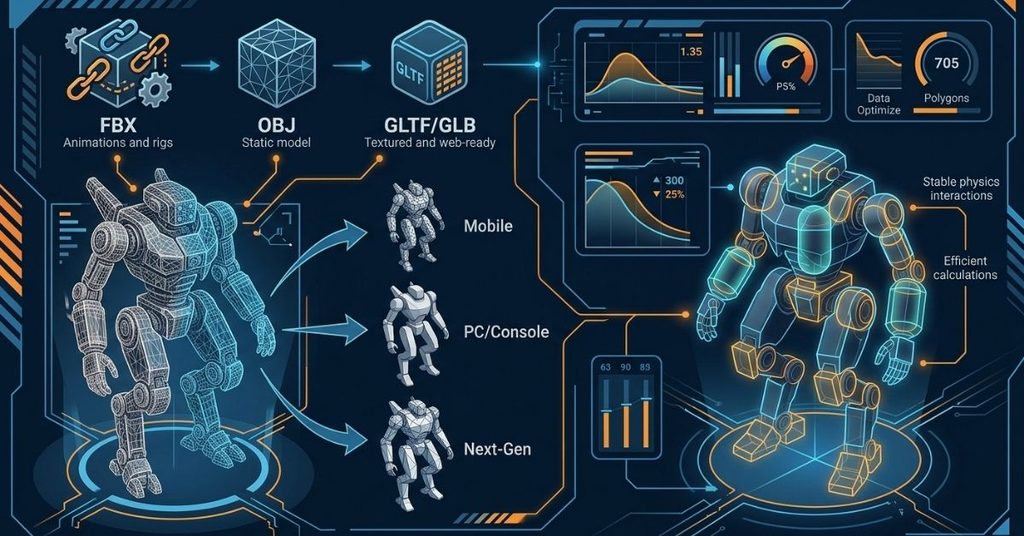
File Format Specifications: FBX, OBJ, and GLTF/GLB
- FBX: The industry standard for game engines. Carries rigs, animations, and material references reliably between Blender/Maya and Unity/Unreal Engine robot asset pipelines.
- OBJ: Static mesh only, no rigging or animation support. Fine for simple props or CAD-style industrial models.
- GLTF/GLB: Built for web and real-time viewers. Ideal for Sketchfab embeds and browser-based 3D robot character design portfolios, since it packages textures and materials into a single efficient file.
Polycount Budgets for PC, Console, and Mobile Assets
Budgets shift constantly as hardware evolves, but general targets still hold up as a starting point:
- Mobile/VR hero character: 8,000–20,000 triangles
- Mid-tier PC/console character: 30,000–60,000 triangles
- Current-gen console hero character: 60,000–150,000 triangles
- Cinematic/VFX asset: 150,000+ triangles, no real-time constraint
Always check your target engine’s actual performance profiling tools rather than relying on generic numbers. A poorly optimized 20,000-triangle asset can outperform a well-optimized 60,000-triangle one.
Setting Up Colliders and Physics Assets in Unreal & Unity
Simplified collision geometry keeps physics calculations cheap. Never use your render mesh directly as a collider. Build simple capsule, box, or convex hull shapes around major body parts instead. In Unreal Engine, this means setting up a Physics Asset with properly weighted constraints between bodies. In Unity, it usually means a combination of simplified colliders parented to the rig’s major bones.
Sourcing and Selecting 3D Robot Assets
Not every project needs a custom build from scratch. Free 3D robot models and paid marketplace assets can save serious time if you know what to check first. For additional examples and ideas, explore this guide to the best 3D-printed robots.
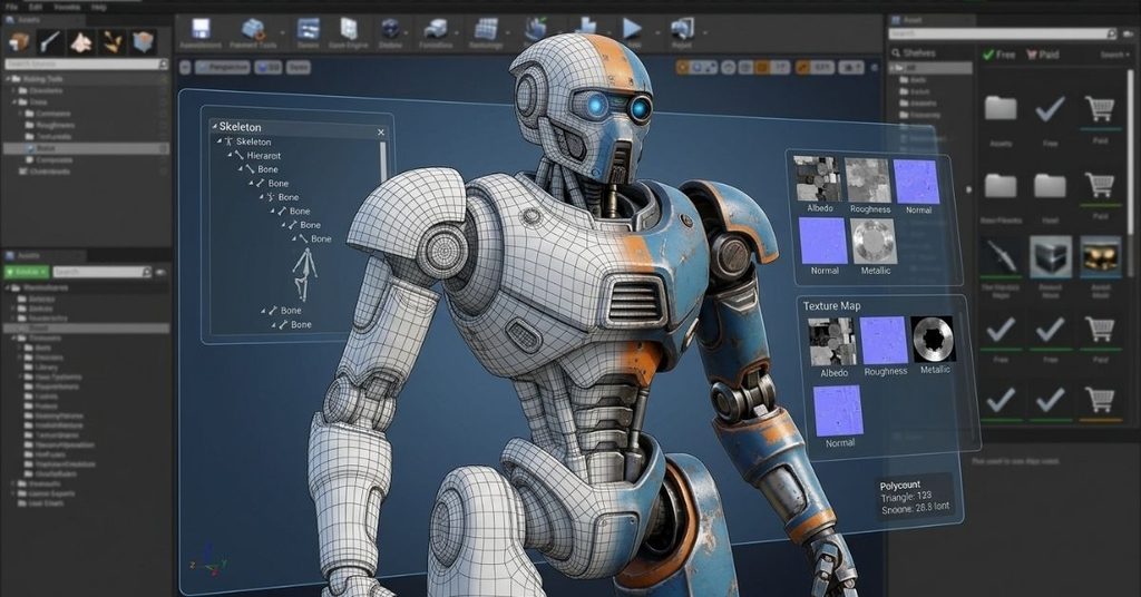
Key Technical Criteria to Evaluate Before Downloading Free Assets
- Topology quality: Open the mesh in wireframe mode. Look for clean quads at joints and no obvious n-gon errors.
- Rig compatibility: Check whether the model includes a rig, and confirm it uses a standard bone hierarchy your engine can read.
- Texture resolution and format: Confirm the PBR maps match your target engine’s expected channel setup.
- Polycount fit: Match the asset’s triangle count to your actual platform target, not just what looks impressive in a marketplace thumbnail.
- File format support: Confirm FBX, OBJ, or GLTF availability, since some free platforms only offer proprietary formats.
Licensing Considerations for Commercial Projects
Free doesn’t always mean free for commercial use. Read the license terms carefully. Some free 3D robot models restrict use to non-commercial or personal projects, while others require attribution. Marketplaces like Sketchfab and ArtStation clearly label licensing terms per asset, but always double-check before shipping a product built around a downloaded model.
Frequently Asked Questions
What’s the best file format for importing robot models into Unreal Engine or Unity?
FBX remains the safest choice for rigged, animated robot models. It preserves bone hierarchies and animation data reliably across both engines.
How many polygons should a game-ready robot model have?
It depends on the platform. Mobile and VR targets usually sit between 8,000 and 20,000 triangles, while current-gen console heroes can run 60,000 to 150,000 triangles.
Should I use IK or FK for a robot rig?
Use IK for legs and situations needing precise foot or hand placement. Use FK for secondary motion like tails, antennae, or upper-arm segments that don’t need exact end-point control.
Can I use free 3D robot models in a commercial game?
Sometimes. Always check the specific license attached to the asset. Some allow commercial use freely; others require attribution or restrict commercial use entirely.
Why does my robot’s mesh pinch or stretch at the joints during animation?
This usually points to insufficient edge loop density at the joint. Add support loops around elbows, knees, and pistons before rigging to prevent this.
What’s the difference between Sub-D and Boolean modeling for hard-surface work?
Sub-D modeling uses clean quad topology and support loops for smooth, production-ready results. Boolean modeling cuts shapes together quickly but usually needs manual topology cleanup afterward.
Conclusion
Building a strong 3D robot model takes discipline at every stage: blockout, hard-surface detailing, texturing, rigging, and export. Skip a step, and it shows up later as clipping geometry, broken IK chains, or a mesh that falls apart under a game engine’s frame budget.
Treat your workflow as one continuous pipeline rather than isolated tasks, and your robot assets will hold up whether they’re running in a mobile game, a AAA console title, or a cinematic VFX shot.

I’m Qasim Ali, the Founder and Technology Writer at TechRised, with 10+ years of experience and a strong academic background in technology and emerging digital innovations. My expertise spans Generative AI, AI Automation, Robotics, Computer Vision, and Machine Learning. I specialize in researching emerging technologies, analyzing industry trends, and transforming complex technical concepts into clear, practical, and reliable insights. Through TechRised, I share research-driven content to help readers understand the latest advancements in AI and the technologies shaping the future.