


Introduction
A robot pivot determines how well a robot arm moves. It sets the reach, the accuracy, and the life of the machine. A weak pivot wastes energy and drifts out of position. A strong one holds tolerance for years.
This guide explains how a robot pivot works. It covers the parts, the drive options, the torque math, the calibration steps, and the failure modes. Engineers, maintenance teams, and buyers can use it as a working reference.
What Is a Robot Pivot?
A robot pivot is a joint that lets one link rotate around a fixed axis relative to another. It connects two arm segments. It also carries the load that passes between them.
Every pivot has three jobs. It guides the rotation, transmits torque, and reports its position to the controller.
Defining the Robot Pivot in Kinematics and Industrial Automation
In kinematics, a pivot is a revolute joint. It gives one degree of freedom (DoF). The joint turns about a single axis, and nothing else moves.
An industrial robot pivot adds hardware to that idea. A bearing carries the load. A reducer multiplies torque. An encoder tracks the angle. Together, these parts form the industrial robot pivot mechanism you see inside a six-axis arm.
The controller treats each pivot as a variable in a chain. It calculates the end-effector position from every joint angle. A small angle error at the base grows into a large position error at the tool tip.
Key Differences Between Fixed-Axis Pivots and Multi-Axis Joint Mechanisms
A fixed-axis pivot rotates around one line in space. A multi-axis joint, such as a wrist or a ball joint, combines two or three rotations in one assembly.
| Feature | Fixed-Axis Pivot | Multi-Axis Joint |
| Degrees of freedom | 1 | 2 or 3 |
| Mechanical complexity | Low | High |
| Stiffness | High | Lower, because of stacked stages |
| Backlash sources | One reducer | Several reducers and couplings |
| Typical use | Base, shoulder, elbow | Wrist, gimbal |
| Maintenance effort | Lower | Higher |
Fixed-axis pivots win on stiffness and simplicity. Multi-axis joints win on compactness at the wrist. Most arms use both.
Essential Components of a High-Precision Robot Pivot
Three subsystems define a robot pivot. Each one limits the final accuracy. Weakness in any of them shows up at the tool.

Precision Bearings: Crossed Roller vs. Angular Contact
Robot pivot bearing selection starts with the load. Look at the moment load, the radial load, and the axial load together.
Crossed roller bearings place cylindrical rollers at right angles in one race. They handle radial, axial, and moment loads in a single compact ring. They suit compact joints that need high stiffness.
Angular contact bearings use balls set at a contact angle. Engineers usually pair them in a face-to-face or back-to-back layout. The pair carries combined loads. Preload adjustment sets the stiffness.
| Bearing Type | Strength | Limit |
| Crossed roller | Compact, stiff, handles moment loads | Needs careful housing tolerances |
| Angular contact (paired) | Adjustable preload, high speed | Takes more space and more parts |
Pick crossed roller bearings when space is tight. Pick angular contact pairs when you need to tune preload or run at higher speed.
Drive Systems: Harmonic Drive, Cycloidal Reducers, and Direct Drive
The drive system turns motor speed into joint torque. Three options dominate.
Harmonic drive. A flexible steel cup deforms against a rigid ring. It offers high reduction ratios in a small, light package. Many harmonic drive robot pivot designs reach very low backlash. Torsional windup under heavy load is the trade-off.
Cycloidal reducer. Lobed discs roll against pins. The design handles shock loads well. It resists wear and carries high torque. It weighs more than a harmonic drive.
Direct drive. A torque motor connects straight to the joint. It has no gears and no backlash. It also needs a large, costly motor to produce high torque.
When designing the joint assembly, engineers can use a 3D robot model to visualize component placement, check clearances, and plan how the motor, reducer, and bearings fit together.
Feedback Systems: Absolute Optical Encoders and Resolvers
The pivot must know its angle. Two sensor types do the job.
Absolute optical encoders read a coded disc. They report position the moment power returns. They give high resolution. Dust and oil on the disc can degrade the signal.
Resolvers work like small rotating transformers. They tolerate heat, shock, and contamination. Their resolution is lower, but the signal conditioning can compensate.
Place the encoder on the output side of the reducer when you want to measure true joint angle. Placing it on the motor side hides reducer windup from the controller.
Comparative Performance Matrix: Robot Pivot Actuator Types
The table below compares the three drive types. The qualitative ratings reflect typical manufacturer positioning.
| Metric | Harmonic Drive | Cycloidal Reducer | Direct Drive |
| Peak torque density | High | High | Low to medium |
| Backlash | Very low | Low | None |
| Shock-load tolerance | Moderate | High | Moderate |
| Thermal drift | Moderate | Moderate | Depends on motor cooling |
| Wear behavior | Flexspline fatigue over time | Slow, even pin and disc wear | No gear wear |
| Relative cost | Medium | Medium to high | High |
Case Study: Resolving High-Backlash Failures in Heavy Automobile Assembly Pivots
An automated welding line began to miss its weld seams. Inspection showed a positioning error of 0.8 mm. The error traced back to wear in one robot pivot.
Step 1: Measure the symptom
The team ran the arm through a repeatable path. They recorded the tool position with a laser tracker. The error grew at the ends of each move. That pattern points to backlash, not a software offset.
Step 2: Find the root cause
The team attached accelerometers to the joint housing. They ran a vibration spectrum analysis during motion. Peaks at the gear mesh frequency and its sidebands showed worn contact surfaces. Looseness in the housing fit made the problem worse.
Step 3: Fix the pivot
The engineers re-machined the pivot housing to restore the bearing fit. They replaced the worn components. They then adjusted the bearing preload to remove free play without overheating the joint.
Step 4: Verify the result
The team repeated the laser tracker test. The line reached a repeatability of better than 0.02 mm. Weld quality returned to spec.
What this case teaches
Track backlash before it reaches weld quality. Measure at the tool, not only at the joint. Treat preload as a maintenance setting, not a one-time assembly value.
The 5-Step Framework for Calculating Ideal Torque and Payload Capacity
Use this framework to size a robot pivot for a pick-and-place or heavy-payload job. Work through the steps in order.

Step 1: Define the load case
List the payload mass, the end-effector mass, the arm length, and the worst-case pose. The worst case is usually a fully extended, horizontal arm.
Step 2: Calculate static torque
Use this formula:
T_static = m × g × L
Here, m is the total mass at the end of the link. g is 9.81 m/s². L is the distance from the pivot axis to the load’s center of mass.
Example: A 10 kg load sits 0.8 m from the axis.
T_static = 10 × 9.81 × 0.8 = 78.5 N·m
Step 3: Add dynamic torque and match inertia
The joint must also accelerate the load. Calculate load inertia first:
J_load = m × L²
J_load = 10 × 0.8² = 6.4 kg·m²
Then multiply by the angular acceleration you need:
T_dynamic = J_load × α
At α = 5 rad/s², T_dynamic = 6.4 × 5 = 32 N·m.
Total torque is 78.5 + 32 = 110.5 N·m.
Next, check inertia matching. Compare the load inertia reflected to the motor with the motor’s own rotor inertia. A large mismatch makes the servo harder to tune. Reducer ratio squared divides the load inertia, so a higher ratio helps.
Step 4: Resolve the load vectors
Split the forces on the bearing into axial and radial components. Add the moment load from the offset payload. Compare each value with the bearing’s rated capacity. Apply a safety factor.
Using a 1.5 safety factor on the example above:
110.5 × 1.5 = 166 N·m required rating
Your application may need a different factor. Check your internal standards.
Step 5: Account for thermal expansion
Metal grows as it heats. Use this formula:
ΔL = α × L × ΔT
Steel expands at about 12 × 10⁻⁶ per °C. Take a 100 mm bore that warms by 30 °C:
ΔL = 12 × 10⁻⁶ × 100 × 30 = 0.036 mm
Aluminum expands at roughly 23 × 10⁻⁶ per °C. The same case gives about 0.069 mm. That change can wipe out a bearing preload. Mixed-material housings need extra care.
Decision shortcut
| If your result shows… | Then… |
| High torque with shock loads | Favor a cycloidal reducer |
| High torque with tight space and weight limits | Favor a harmonic drive |
| Moderate torque with a need for zero backlash | Consider direct drive |
| Large temperature swings | Check preload change before you finalize |
How to Calibrate and Zero-Position a Robot Pivot
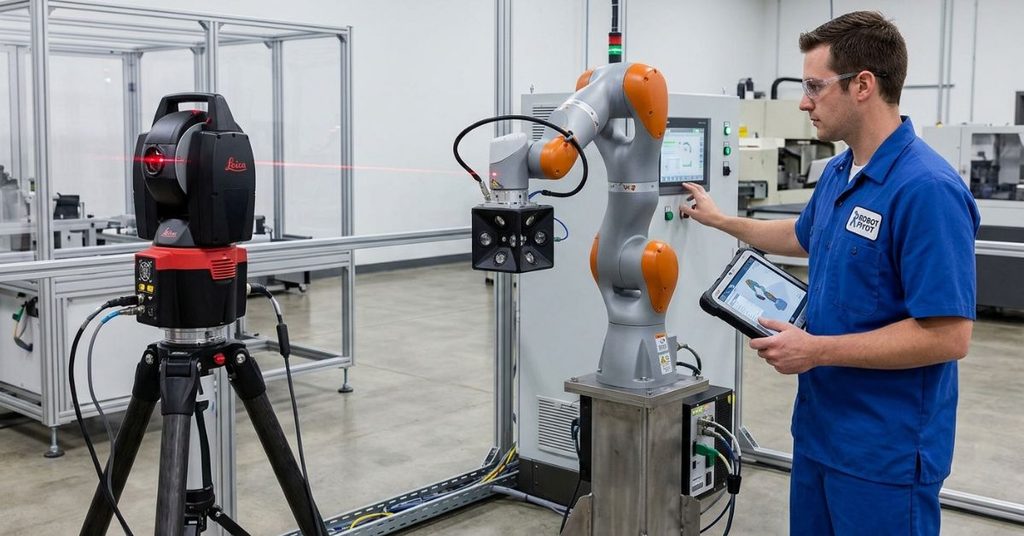
Calibration links the controller’s model to the real arm. Without it, even a perfect pivot misses its target. ISO 9283 defines how to test pose accuracy and repeatability, so use it as your test reference.
Laser Tracker Alignment Protocols
A laser tracker measures the tool position in 3D. Follow these steps.
- Let the robot warm up. Run it through typical motions first.
- Mount the tracker target on the end-effector.
- Move each joint through its range. Record the positions.
- Measurement and command paths should be compared.
- Repeat the test at several loads.
- Log the ambient temperature.
- Save the results as your baseline.
Software Offset Calibration: Adjusting Kinematic Parameters
The measured error feeds a correction. Software adjusts the kinematic parameters, such as link lengths and joint zero offsets. The controller then plans moves with the corrected model.
Take these precautions:
- Back up the original parameters first.
- Change one parameter group at a time.
- Retest after each change.
- Record every adjustment in the maintenance log.
Software cannot fix mechanical backlash. If the error changes with direction, repair the hardware first.
Preventing Failure in Heavy-Duty Robot Pivot Assemblies
Most pivot failures give a warning. Heat rises. Noise changes. Accuracy slips. A routine catches these signs early.
Thermal Management and Heat Dissipation Strategies
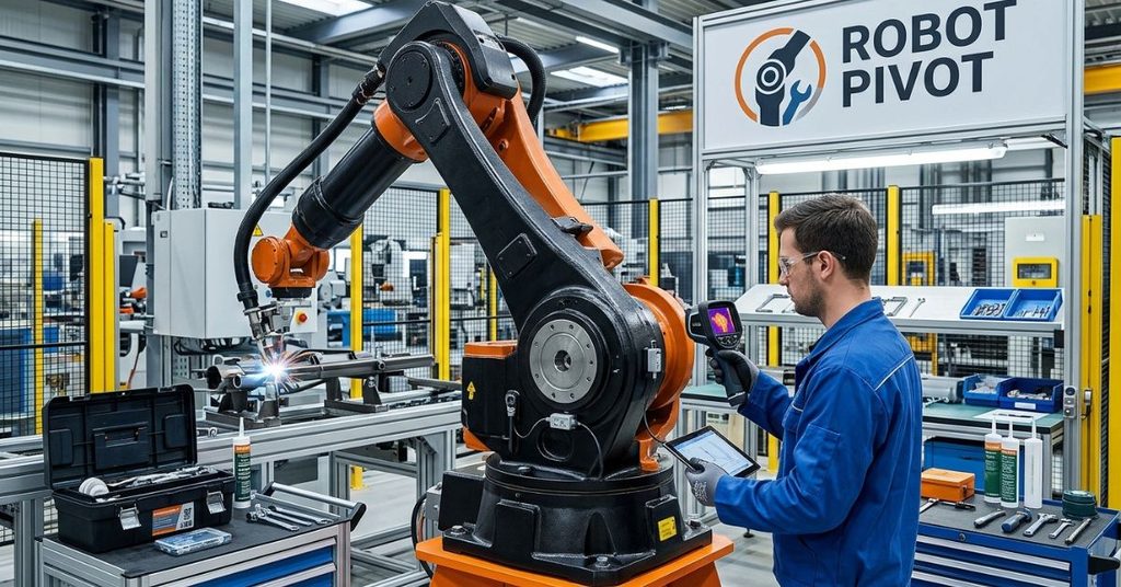
Heat comes from motor losses, gear friction, and bearing friction. Too much heat degrades grease, shifts preload, and shortens seal life.
Use these controls:
- Keep airflow clear around joint housings.
- Add heat sinks or cooling fins on high-duty joints.
- Reduce duty cycle where the process allows.
- Monitor housing temperature with a simple sensor.
- Let the robot reach thermal balance before precision work.
Lubrication Schedules and Grease Selection Matrix
Follow the reducer manufacturer’s grease type and interval. Never mix greases without checking compatibility. Different thickeners can break down when they combine.
| Joint Condition | Lubrication Focus |
| Harmonic drive, normal duty | Use the grease the maker specifies. Keep fill quantity exact. |
| Cycloidal reducer, shock loads | Check the grease for metal particles. Shorten the interval if needed. |
| High-temperature cell | Choose a grease rated for the temperature. Inspect seals often. |
| Washdown or dusty site | Inspect seals. Replace damaged ones right away. |
Over-greasing causes heat and seal damage. Under-greasing causes wear. Measure the fill, and log each service.
Wear Detection Techniques Using Vibration Sensors
Vibration sensors catch wear before the tool shows it. Mount accelerometers near each pivot. Record a baseline spectrum when the joint is healthy.
Then watch for these changes:
- New peaks at the gear mesh frequency
- Rising sidebands around those peaks
- Higher overall vibration at the same speed
- Shifts that appear only in one rotation direction
Trend the readings over weeks. A steady climb tells you to schedule service. A sudden jump tells you to stop the robot and inspect.
Frequently Asked Questions
What is a robot pivot?
A robot pivot is a revolute joint that lets one arm link rotate about a single axis. It combines a bearing, a drive, and a position sensor.
What causes backlash in a robot pivot?
Backlash comes from gear clearance, worn parts, and loose bearing fits. Repeated shock loads and poor lubrication speed up wear.
Which drive suits a robot pivot best?
It depends on the job. Harmonic drives suit compact, light designs. Cycloidal reducers suit heavy loads and shocks. Direct drive suits applications that need zero backlash.
How often should I calibrate a robot pivot?
Calibrate after any mechanical repair, collision, or part replacement. Also calibrate on a schedule that matches your accuracy needs. High-precision work needs more frequent checks.
How do I calculate the torque a robot pivot needs?
Add static torque (mass × gravity × arm length) and dynamic torque (inertia × acceleration). Then apply a safety factor.
Can software fix a worn pivot?
No. Software corrects geometry errors and zero offsets. It cannot remove free play in worn parts.
What does ISO 9283 cover?
ISO 9283 sets test methods for the pose accuracy and repeatability of industrial robots. Many teams use it to verify calibration results.
Conclusion
A robot pivot looks simple. It holds a lot of engineering. The bearing, the drive, and the encoder each shape accuracy. The torque math sets the size. Calibration and maintenance keep it accurate.
Start with the load case. Size the torque with margin. Pick the drive that fits your space, shock, and backlash needs. Calibrate with a laser tracker. Track vibration and heat to catch wear early.
Apply these steps and your pivots will hold position longer and cost less to run.

I’m Qasim Ali, the Founder and Technology Writer at TechRised, with 10+ years of experience and a strong academic background in technology and emerging digital innovations. My expertise spans Generative AI, AI Automation, Robotics, Computer Vision, and Machine Learning. I specialize in researching emerging technologies, analyzing industry trends, and transforming complex technical concepts into clear, practical, and reliable insights. Through TechRised, I share research-driven content to help readers understand the latest advancements in AI and the technologies shaping the future.