


Introduction
Cutting sits at the start of almost every fabrication job. A slow or inaccurate cut hurts every step after it.
For decades, shops relied on flat-bed machines and skilled manual operators. Those tools still work well. But they struggle with curved parts, tall parts, and short production runs.
Robotic cutting technology fills that gap. A robot arm moves a cutting tool through three-dimensional space. It follows a programmed path, and it can reach angles a gantry cannot.
This guide explains how the technology works. It compares the main cutting processes. It also gives you a selection method, a case study, and a safety overview.
What Is Robotic Cutting Technology?
Robotic cutting technology uses an industrial robot to carry a cutting tool along a programmed path. The tool can be a plasma torch, a laser head, a waterjet nozzle, or a router. The robot replaces the fixed axes of a traditional cutting table.
Most systems use a six-axis articulated arm. Six axes let the tool approach a part from nearly any direction. That flexibility makes 3D cutting practical.

Key Components: Robot Arm, Controller, EOAT, and Tool Center Point (TCP)
Every robotic cutting cell shares the same core parts.
- Robot arm: It positions and orients the tool. Payload and reach set the limits.
- Controller: It runs the motion program and talks to the cutting source.
- End-of-arm tooling (EOAT): This is the torch, laser head, nozzle, or spindle. It attaches to the robot wrist.
- Tool center point (TCP): This is the exact point on the tool that does the work. The controller must know where it sits.
- Power source or beam source: It supplies plasma current, laser light, or high-pressure water.
- Safety enclosure: Fencing, light curtains, and interlocks protect people.
TCP setup matters more than most beginners expect. A small TCP error becomes a cutting error on the part. Teams calibrate it carefully and re-check it after any collision or tool change.
Robotic Cutting vs. Traditional CNC Machining: A Direct Comparison
Neither approach wins everywhere. Each fits different work.
| Factor | Robotic Cutting | Traditional CNC |
| Reach and angles | Strong on 3D and complex shapes | Limited to the machine’s axes |
| Rigidity | Lower, because of the arm’s joints | Higher, because of the machine frame |
| Absolute accuracy | Lower unless calibrated | Typically higher |
| Repeatability | Good | Very good |
| Part size flexibility | High, with the right cell layout | Fixed by table size |
| Fixture needs | Often lower | Often higher |
| Best fit | Varied, curved, or large parts | High-precision flat or prismatic work |
Robots repeat a move more precisely than they hit an absolute position. Calibration and sensors close much of that gap. For very tight tolerances, a CNC machine often remains the safer choice.
Core Processes Powered by Robotic Cutting Technology
Each process suits different materials. Pick the process first. Then pick the robot.
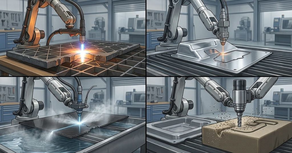
Robotic Plasma Cutting Systems
Plasma cutting uses a hot, ionized gas jet to melt metal. It works only on electrically conductive materials. Aluminum, stainless steel, and mild steel are all included.
Plasma handles thick plate well. Equipment costs less than laser equipment. Robots add bevel cuts and 3D profiles, which suit structural steel work.
Plasma leaves a wider kerf and a larger heat-affected zone than laser. Teams often clean up the edge when the part needs a fine finish.
Robotic Laser Cutting Automation (Fiber vs. CO₂)
Laser cutting focuses a beam to melt or vaporize material. Fiber lasers and CO₂ lasers both serve industry.
Fiber lasers dominate metal cutting today. They cut reflective metals such as aluminum and copper alloys more easily than CO₂ lasers. They also need less maintenance because they have no mirrors to align in the beam path.
CO₂ lasers still serve some non-metal work. They cut materials like wood, acrylic, and some plastics.
A robot-mounted laser head cuts formed and tubular parts. Beam delivery needs careful calibration. The focus distance must stay constant as the arm moves.
Robotic Abrasive Waterjet Cutting
A waterjet pushes water through a tiny nozzle at very high pressure. Garnet is added to abrasive waterjets to cut hard materials. This process cuts metal, stone, glass, and composites.
Waterjet cutting generates no heat-affected zone. That makes it a strong choice for heat-sensitive parts. Carbon fiber and layered composites benefit from this.
Waterjet cutting runs slower than laser on thin sheets. It also creates abrasive waste and needs nozzle upkeep. Robotic waterjet cells must manage the jet’s reaction force and the wear on the nozzle.
Robotic Routing, Milling, and Mechanical Trimming
Robots also carry spindles. They route foam, plastic, wood, and composite parts. They trim molded parts at the edges.
For a broader look at how robots support industrial cutting and manufacturing workflows, explore our guide to Chirp Robotics.
Lower rigidity limits this process. The arm can chatter under heavy loads. Light cuts on soft materials work best. Hard metals usually belong on a rigid machine tool.
Performance & ROI Matrix: Comparative Benchmark Data
Exact numbers depend on your material, thickness, and equipment. So treat any benchmark as a starting point, not a promise. The matrix below ranks the three main processes in general terms.
| Factor | Plasma | Laser (Fiber) | Abrasive Waterjet |
| Materials | Conductive metals only | Most metals; some non-metals | Nearly any material |
| Edge quality | Fair to good | Excellent on thin material | Good to excellent |
| Heat-affected zone | Largest | Small | None |
| Thickness strength | Medium to thick plate | Thin to medium | Thin to very thick |
| Cutting speed | Fast on plate | Very fast on thin sheet | Slowest of the three |
| Equipment cost | Lowest | Highest | Medium to high |
| Operating cost | Low | Low to medium | Highest, due to abrasive and pump wear |
| Best fit | Structural steel, heavy plate | Precision sheet and tube work | Composites, heat-sensitive parts |
How to Read the Numbers for Your Shop
Run your own test cuts before you buy. Cut your real materials at your real thicknesses. Measure edge quality, cycle time, and consumable cost.
Then split your work into two groups. Short runs value flexibility and quick changeovers. High-volume runs value speed and low cost per part. A robot often wins on the first group. A dedicated machine can win on the second.
Software, Offline Programming (OLP), and Path Accuracy
Software decides how quickly you can put a robot to work. It also decides how safe the first run will be.

From CAD to Cut: The Programming Workflow
The workflow follows four steps.
- Start with the CAD model of the part.
- Generate tool paths in CAM or offline programming (OLP) software.
- Post-process the paths into robot controller code.
- Run the program, with the controller driving the TCP along the path.
OLP lets you program the robot on a computer. You do not need to stop the cell and teach points by hand. You can also simulate the cell and spot collisions before the robot moves.
Path Accuracy and Tolerance Control
Several factors affect the cut path.
- Calibration: Robots need calibration to improve absolute accuracy.
- Heat distortion: Thermal processes can warp the part during cutting.
- Fixture variation: Parts do not always sit in the same spot.
- Tool wear: Nozzles and electrodes change the cut over time.
Sensors address these problems. Touch sensing, laser seam tracking, and vision systems find the real part position. The controller then adjusts the path to match.
Case Study: Aerospace Transition to 6-Axis Robotic Cutting Technology
A mid-sized aerospace supplier trimmed curved carbon-fiber composite components on a 5-axis CNC machine. Each part shape needed its own hard tooling. Changeovers took time, and scrap added cost.
The supplier replaced the setup with an articulated 6-axis robotic cutting cell.
The Results
| Metric | Result |
| Fixture re-tooling time | 65% reduction |
| Cycle time on complex 3D trimming | 42% faster |
| Scrap rate | 4.2% down to 0.3% |
What Went Wrong First
The team hit two problems during commissioning.
First, TCP calibration drifted. Small errors in the tool definition produced visible path errors. The team fixed this with a stricter calibration routine and regular checks.
Second, heat distortion moved the seam during cutting. The programmed path no longer matched the real part. The team added sensor-guided seam tracking. The robot then corrected its path in real time, and the drift stopped.
The lesson is simple. Calibration and sensing decide whether a robot cell performs well. The robot alone does not.
The “R.O.B.O.T.” Selection Methodology for Engineering Teams
This five-point method helps integrators choose and validate a cutting cell. Work through the letters in order.
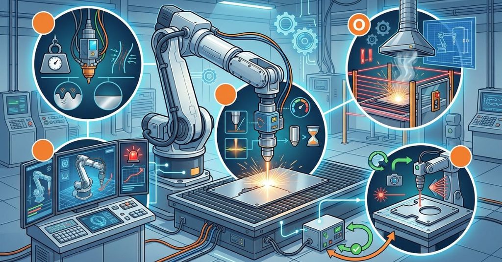
R: Rigidity & Payload Assessment
Check the arm’s payload against the full end-effector weight. Include cables, hoses, and any sensors. Then judge dynamic chatter. A robot that vibrates under cutting loads will leave a poor edge.
O: Offline Programming & Digital Twin Compatibility
Confirm that your OLP software supports your robot brand and cutting process. Build a digital twin of the cell. Simulate every path and catch collisions before production starts.
B: Beam/Jet Delivery Calibration
Verify torch angle, kerf compensation, and focus distance. Set nozzle wear rules so the controller or operator replaces parts on time. This step protects cut quality across a long run.
O: Overhead & Safety Integration
Plan light curtains, interlocks, and fume extraction at the design stage. Do not bolt them on later. Thermal cutting produces fumes and sparks, and each hazard needs a control.
T: Tolerance & Metrology Feedback Loops
Add in-line measurement where tolerances are tight. Optical sensors can check the part and feed corrections back to the path. This loop keeps quality steady as conditions change.
Safety, Enclosures, and Regulatory Compliance (OSHA / ISO Standards)
Robotic cutting cells combine moving machinery with heat, light, or high pressure. Safety needs a plan from day one.

Key Standards to Know
- OSHA: In the U.S., OSHA sets workplace safety rules and enforces them.
- ISO 10218: This standard covers safety requirements for industrial robots and robot systems.
- ANSI/RIA R15.06: This is the U.S. adoption of the industrial robot safety standard.
- Laser safety standards: Laser cells need beam enclosure and operator protection rules.
Standards change over time, so check the current editions. A qualified safety professional should review your final design.
Practical Safety Controls
- Use guarded enclosures with interlocked doors.
- Install light curtains at load and unload points.
- Add emergency stops that reach every operator position.
- Extract fumes at the source for plasma and laser work.
- Shield operators from laser light and waterjet spray.
- Train staff on lockout and restart procedures.
Future Trends: AI-Driven Sensor Guidance, Adaptive Path Tracking, and Cobots
Three trends stand out.
Sensor-guided adaptation. Vision and laser scanners already let robots find a part and adjust the path. Software is improving at doing this faster and with less setup.
AI-assisted programming. Vendors now use machine learning to help generate paths and detect defects. Results vary by product, so test any such tool on your own parts.
Collaborative robots. Cobots can work near people without full fencing, under the right risk assessment. Their payload and speed are limited. Heat and beam hazards still call for protection. Cobots fit light tasks such as small-part trimming more than heavy plasma work.
Frequently Asked Questions
What is robotic cutting technology?
It is the use of an industrial robot to move a cutting tool along a programmed path. The tool can be a plasma torch, laser head, waterjet nozzle, or router.
Is robotic cutting more accurate than CNC cutting?
Usually not in absolute terms. CNC machines are typically more rigid and accurate. Robots repeat motions well and can reach complex angles. Calibration and sensors improve their accuracy.
Which robotic cutting process is best?
It depends on your material and part. Plasma suits thick conductive metals. Fiber laser suits precise work on thin to medium metal. Waterjet suits heat-sensitive materials and composites.
Can one robot handle more than one cutting process?
Yes, with a tool changer. Many cells swap between tools. Each process still needs its own power source, safety controls, and calibration.
How do I calculate the ROI of a robotic cutting cell?
Add up your current labor, scrap, and changeover costs. Estimate the same costs with a robot. Include equipment, installation, programming, training, and maintenance. Divide the total investment by the yearly savings to estimate the payback period.
What safety measures does a robotic cutting cell need?
It needs guarded enclosures, interlocks, light curtains, emergency stops, and fume extraction. Laser and waterjet cells need extra protection. Follow current OSHA and ISO rules.
Do I need offline programming software?
You can teach points by hand for simple jobs. For complex 3D parts, OLP saves time and lowers risk. It also lets you test paths without stopping production.
Conclusion
Robotic cutting technology gives fabricators flexibility that fixed machines lack. A six-axis arm reaches complex shapes. The right process adds the cutting power.
Success depends on good choices. Match the process to your material. Calibrate the TCP and the beam or jet. Add sensors where tolerances are tight. Plan safety from the start.
Use the R.O.B.O.T. method to guide your selection. Run test cuts on your own parts. Then build the ROI case with your own numbers.

I’m Qasim Ali, the Founder and Technology Writer at TechRised, with 10+ years of experience and a strong academic background in technology and emerging digital innovations. My expertise spans Generative AI, AI Automation, Robotics, Computer Vision, and Machine Learning. I specialize in researching emerging technologies, analyzing industry trends, and transforming complex technical concepts into clear, practical, and reliable insights. Through TechRised, I share research-driven content to help readers understand the latest advancements in AI and the technologies shaping the future.